Pass4Future also provide interactive practice exam software for preparing AutoDesk Certified Professional in Revit for Electrical Design (RVT_ELEC_01101) Exam effectively. You are welcome to explore sample free AutoDesk RVT_ELEC_01101 Exam questions below and also try AutoDesk RVT_ELEC_01101 Exam practice test software.
Do you know that you can access more real AutoDesk RVT_ELEC_01101 exam questions via Premium Access? ()
Refer to exhibit.

An electrical designer is placing electrical equipment. When the electrical designer selects a component in the contextual ribbon, the Placement panel appears in the contextual ribbon.
Which condition does this Placement panel indicate?
Answer : B
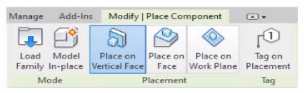
The Placement panel shown in the exhibit --- with options such as Place on Vertical Face, Place on Face, and Place on Work Plane --- is displayed only when the family being placed was created using a wall-hosted (face-based or vertical face-based) template. This indicates that the family is designed to be hosted on a vertical surface, such as a wall, rather than a floor or level.
According to the Autodesk Revit MEP User's Guide (Chapter 44 ''Creating and Modifying Families''):
''When placing a hosted family, the placement options depend on the family's host type.
Wall-based families display the Place on Vertical Face option.
Ceiling-based families display Place on Face or Place on Work Plane.
Floor-based families display Place on Work Plane only.''
The ''Place on Vertical Face'' option specifically appears for wall-hosted or face-based components because it allows the user to select a vertical plane, typically representing a wall surface. This confirms that the family template used during creation was Wall-based (commonly ''Electrical Equipment - Wall Based.rft'' or ''Generic Model - Wall Based.rft'').
In electrical design, examples of such components include:
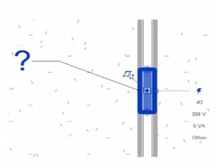
Wall-mounted panelboards, switchboards, or transformers.
Receptacles or lighting control devices hosted on walls.
The Smithsonian Facilities Revit Template Guide reinforces this explanation:
''Wall-based components, such as surface-mounted panels, display the Place on Vertical Face option. This confirms the family is wall-hosted and cannot be placed freely on floors or reference planes.''
Why the Other Options Are Incorrect:
A . Face-based template: Would show ''Place on Face'' (not necessarily limited to vertical).
C . Floor-based template: Displays ''Place on Work Plane'' only.
D . Always Vertical option: Controls orientation (rotation relative to surface), not placement host type.
Therefore, the Placement panel confirms the component was created using a wall-based family template, allowing it to be attached only to vertical surfaces.
References:
Autodesk Revit MEP User's Guide -- Chapter 44 ''Creating and Modifying Families,'' pp. 1028--1032
Smithsonian Facilities Revit Template User's Guide -- Section 7.4 ''Family Hosting and Placement Behavior,'' pp. 72--74
Autodesk Revit Electrical Design Essentials -- ''Wall-Based Equipment and Hosting Parameters in Family Creation''
Exhibit.

An electrical designer creates a panel schedule. Which Electrical Equipment parameter defines the default name of the panel schedule view?
Answer : D
In Autodesk Revit for Electrical Design, when a designer creates a panel schedule, the default name of the panel schedule view is automatically derived from the Panel Name parameter of the Electrical Equipment family to which the circuits are assigned.
According to the Revit MEP User's Guide (Electrical Systems section: Panel Schedules):
''When you create a panel schedule, Revit uses the Panel Name parameter of the electrical equipment to define the default schedule name. The Panel Name identifies the distribution panel that supplies the circuits. This name appears in both the Panel Schedule view and in circuit information tags.'' --- Revit MEP User's Guide, Chapter 17: Electrical Systems -- Panel Schedules
The Panel Name is a critical electrical equipment instance parameter located in the Electrical -- Circuiting group of properties. It appears in both the Electrical Equipment Properties Palette and the Panel Schedule Header. This name can later be modified manually, but by default, it directly controls the naming convention of the generated schedule.
In contrast:
A . Type Mark --- identifies types within the family for documentation and does not control schedule naming.
B . Mark --- a unique instance identifier often used for tags, but not for panel schedule view naming.
C . Description --- provides descriptive text only for documentation or labeling.
D . Panel Name --- correctly defines and drives the default schedule view name for panels and circuits.
When a panel (electrical equipment) is placed in the model and circuits are connected, Revit generates a new Panel Schedule View automatically titled using the value entered in the Panel Name field (e.g., ''Panel LP-1''). This ensures consistency between the modeled equipment and the schedule documentation.
Verified Reference Extracts from Revit for Electrical Design Documentation:
Autodesk Revit MEP User's Guide (2011), Chapter 17: Electrical Systems -- Creating and Editing Panel Schedules:
''The name of the panel schedule view is determined by the Panel Name property of the electrical equipment.''
Revit MEP Electrical Design Training Manual, Module: Electrical Equipment and Panel Schedules:
''Panel Name is used by Revit as the default identifier for any panel schedule view created for that equipment.''
An electrical designer is adding lights to a project model. The coiling grids arc located in a linked Revit model. How are these lights affected if the grid patterns move?
Answer : A
When working in Autodesk Revit for MEP Electrical Design, lighting fixtures can be either hosted (such as ceiling-hosted or wall-hosted) or non-hosted. The movement of lighting fixtures in relation to linked model elements---like ceiling grids---is determined by the hosting condition and alignment constraints applied to those elements.
According to the Revit MEP User's Guide (Chapter 24 ''Ceilings'' and Chapter 50 ''Rendering''), a ceiling is a level-based element. You can create it on a specified level and host ceiling-based families such as lighting fixtures. When a ceiling is modified or repositioned, the hosted lighting fixtures will move with the ceiling itself, maintaining their relationship to the host surface. However, when ceiling grid patterns are changed or moved in a linked Revit model, the movement of those grid patterns does not automatically propagate to hosted elements in the electrical model unless those elements are directly linked or constrained to a movable reference plane.
As described:
''Ceilings are level-based elements... When you create a ceiling, you can host components such as lighting fixtures on its face. Hosted elements remain associated with their host even if the ceiling is modified.''
And further in the glossary section:
''Rehost: To move a component from one host to another. For example, you can use the Pick New Host tool to move a window from one wall to another wall.''
This confirms that a hosted light fixture maintains its attachment to the host element (the ceiling) but not to the grid pattern itself. Grid movement within a linked ceiling model does not alter the position of lights unless they are manually re-hosted or alignment-locked directly to a specific geometry within the host model.
Therefore, the correct interpretation is that when ceiling grid patterns move within a linked Revit model, the lights placed in the electrical model do not follow the grid pattern movement automatically. They remain stationary relative to the ceiling surface, provided they are hosted correctly.
This behavior reflects Revit's parametric relationships --- ''hosted elements maintain dependency only on their host, not on graphical references like grids unless locked via constraints.''
References:
Autodesk Revit MEP User's Guide, Chapter 24 ''Ceilings'', pp. 579--583
Autodesk Revit MEP User's Guide, Chapter 50 ''Rendering'' (Lighting Fixtures and Hosts)
Autodesk Revit Glossary: ''Rehost'' definition, p. 2037
Revit Electrical Design Parametric Model Behavior -- Revit MEP Essentials
Refer to exhibit.
A portion of an electrical fixture family's Type Properties is shown in the exhibit.

Because of the value of the Type Parameter Load Classification, an electrical designer expects the fixture's Load Classification to display as -Receptacle" when circuited. Instead, it displays as "Other".
What should the designer do to make the circuited fixture's Load Classification always match the family's Type Parameter?
Answer : A
In Autodesk Revit Electrical Design, each electrical family (such as a receptacle, lighting fixture, or equipment) can contain one or more connectors that define how it interacts with the electrical system. The Load Classification parameter determines how the connected load is categorized in electrical schedules and load calculations (e.g., Lighting, Power, Receptacle, Other).
When a family's Type Parameter Load Classification does not display correctly (e.g., it shows ''Other'' instead of ''Receptacle'' after being circuited), the issue lies in the power connector's internal parameter not being linked to the family-level ''Load Classification'' parameter. Revit uses the connector's classification to determine the load type when it is connected to a circuit --- if the connector isn't associated, the classification defaults to ''Other.''
According to the Autodesk Revit MEP User's Guide (Chapter: Electrical Systems -- Creating Electrical Families), it specifies:
''To control how a component reports its connected load type, associate the power connector's Load Classification parameter with a corresponding Family Parameter. This ensures the load classification in the circuit matches the family definition, rather than defaulting to 'Other.' To correct existing families, edit the family in Family Editor, select the connector, and associate its Load Classification parameter with the family's Load Classification type parameter. Then reload the family into the project.''
This confirms that the correct approach is to edit the family and create or link the Load Classification parameter to the connector's Load Classification field. Merely changing the connector value (option C) won't ensure dynamic synchronization between the family type and circuit. Deleting and re-adding the connector (option B) won't automatically create that link. Option D (editing through the System Browser) modifies instance-level data, not family associations.
Hence, the correct and permanent fix is:
Open the family in the Family Editor.
Select the power connector.
In the Properties palette, click the small Associate Family Parameter button () next to Load Classification.
Link it to the family's Load Classification parameter.
Save and reload the family into the project.
References:
Autodesk Revit MEP 2011 User's Guide, Chapter 53: Creating Electrical Families, pp. 1254--1257.
Smithsonian Facilities Revit Template User's Guide (2021), Section 8.3. Electrical Design: Power Connector Parameters.
Autodesk Revit 2020 Help: ''Associate a Connector Parameter with a Family Parameter.''
Refer to exhibit.

Why is Synchronize with Central disabled?
After enabling collaboration for a project, an electrical designer observes the ribbon.
Answer : D
In Autodesk Revit, the Collaborate tab provides the tools necessary for managing multi-user worksharing environments. The Synchronize with Central command allows users to save their local changes back to the central model. However, this command becomes disabled under certain conditions --- most notably when the user is currently working directly within the central file rather than a local copy.
The Autodesk Revit User's Guide -- Worksharing and Collaboration section clearly explains this behavior:
''When you open the central file directly, the Synchronize with Central option is unavailable because all edits are already in the central file. Worksharing operations such as borrowing, relinquishing, or synchronization only apply to local copies created from the central model.''
This rule ensures that the integrity of the central model is preserved and that no user directly edits or synchronizes within it, preventing potential file corruption. In normal collaborative workflows, users open local copies of the central model. The local files maintain an editable subset of elements while allowing synchronization and relinquishing operations.
Thus, the disabled Synchronize with Central button (as shown in the exhibit) indicates that the designer is currently in the central model, not a local copy. Since synchronization is unnecessary in this state --- all changes are automatically applied to the central file --- the command is grayed out.